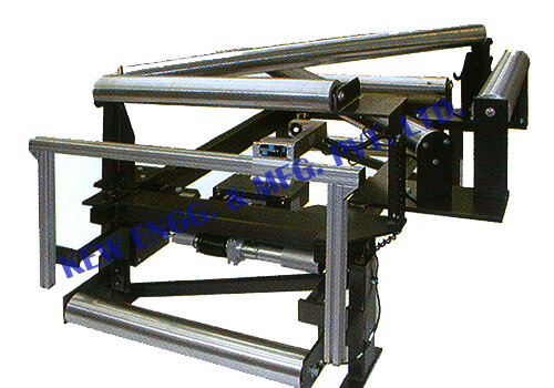
Turn Bar System

Standard Features
It consists of two rectangular steel tubing frames. One is stationary, the other is movable. it is supported in a nyalguide sliding block and arcuate bar system, and has ab idler roller at either end.
The web can be fed over the TRA in A ‘U’ shaped path, reversing its direction of travel, or through the TRA in a ‘Z’ configuration, maintaining the same direction of travel. It is insensitive to attitude and can even be mounted upside down. Solidly supported on all four corners by nylaguide bearings, it is not subject to deflections caused by cantilever stresses. Radial bearings are sealed, and linear bearings are self – cleaning and self – lubrication. The unit therefore requires no maintenance.
We have been manufacturing, exporting, and supplying Turn Bar System from last 25 years. High quality and heavy duty Turn Bar System, India.
Technical Specification
Turn Bar System
- Air Turner Bar Systems are designed and manufactured to suit customers’ particular application. There are six sizes for 90° entry or 180° turnover, with web widths ranging from 100mm to 3 meters, for horizontal or vertical mounting.
- The units are built as freestanding or bolt-on modules, complete with leveling braces and bolting down holes. They are designed to suit existing machine and site conditions.
- The framework is rectangular hollow section with specialized corner bracing incorporating the fine adjustment mechanism and mounting for the Turner Bars.
- Bars are tubular steel with bell mouth air holes, ground, polished and hard chrome plated. Air blow creates an air film assist to the bar.
- By choosing appropriate mounting positions, a variety of configurations can be obtained to enable a choice of entry and exit requirements.
- Path rollers are normally aluminum, statically or dynamically balanced.
- Air for flotation requires 5 CFM per 100mm web width at 10ins to 18ins W.G. depending on web tensions.
- Fans direct mounted on each Turner Bar can be supplied at the time of manufacture (option). For narrow web widths and special applications air flotation holes can be reduced for using compressed air or arranged as required.
